|
Tuning the Pietta
Remington New Army Revolver |
|
Mohave Gambler
|
|
Introduction to the Project |
| One of the most popular Cowboy Action cap
and ball revolvers is the Remington New Army Revolver made by Pietta of
Italy. The reason for the popularity of this old gun is that it is
very affordable. New .44 caliber revolvers can be purchased for as
little as $140, which makes it one of the best bargains in shooting today.
This is my fourth Remington revolver and my second in all-steel. There
are claims that the brass frame versions were used by the confederate army
because of the shortage of steel in the southern states, but I have not seen
any evidence that these revolvers were made in anything but steel. |
|
 |
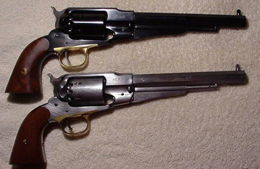
Figure 1. The two Remington New Army revolvers
used for this article. The new one is on top and the old one is below.
The old one is in the "white" with bare metal and has been shot in matches
in both California and Arizona. White guns tend to look a little larger than
their blued counterparts.. |
| The Remington New Army Revolver is often
referred to as the 1858 Remington. This is because the New Army
Revolver is an evolution of the original Beals 1858 patent. The
current reproduction 1858 Remington revolvers are closest to the Remington
New Army Revolver that was manufactured between 1863 and 1888. I like
to refer to these revolvers as the New Army model. |
| The New Army revolver was popular because
of its stopping power and light weight. The use of a top strap that
turns the frame into an "O" shape provides a lot of strength for the amount
of steel being used. In addition, the barrel is screwed solidly into
the frame of the gun and the rear sight is machined into the frame.
Once the New Army is properly sighted in, it will not change because of
parts wear like the Colts. The problem with the Remington design
happens to be caused by the very tightness built into the "O" type frame. |
| The use of blackpowder in cap and ball
revolvers results in a lot of unburned particulates being left over as a
byproduct of the explosion. These revolvers were designed to be used
in battle and not immediately reloaded. A Cowboy shooting match will
typically put thirty shots through a gun in about three hours of shooting.
Colt revolvers seem to shoot much longer without becoming fouled by
blackpowder residue and I have often heard it is because the are built to
much looser tolerances. This is not really true. |
| A comparison of the Colt and Remington
designs will reveal three significant design differences. First is the
absence of the top strap on the Colt allows the powder residue that leaks
out of the barrel to cylinder gap to escape straight out into the air above
the revolver. The Remington top strap deflects some of the escaping
residue back into the action at the front of the cylinder. Second is
the larger cylinder axle, or arbor, and it appears to be threaded, which
provides a place for the powder fouling to be retained in a manner similar
to the treads of a tire. The Remington has a smaller cylinder that is
smooth and provides no place for the fouling to go but between the moving
parts. Third is the fact that Colts have a gap between the cylinder
and the frame that allows most of the powder fouling to escape out the side
of the frame. The Remington has a gap between the cylinder and frame
that is in alignment with the barrel to cylinder gap. This allows
powder fouling to be forced between the cylinder pin and either the cylinder
or the frame. The result is a cylinder that does not want to turn. |
|
Let's Begin |
| I like to begin a project by
evaluating what I have and then establishing my objectives and outcomes.
I started by doing a visual inspection of the new gun and found minor rust
throughout the internal sections of the frame, inside the cylinders, in the
housing area for the hand, and on the cylinder pin. One of the wood
grips had a very minor chip in the curved area just to the rear of the
trigger guard. The hand spring does not fit properly and allows the
hand to be very loose. An inspection of the gun's timing shows that
the hand is too long, which is confirmed by the fact that metal at the tip
of the hand is already wearing away where it binds against the star.
There is a lot of roughness in the hammer cocking and the loading lever seem
to be binding a little. I estimate the trigger pull to be around ten
pounds and the hammer cocking to be close to 25 pounds. The greatest
potential problem is with the barrel to cylinder gap, which measured in at
.003 inches. My more successful revolvers tend to measure about .010
making this gun the tightest cap and ball revolver I have worked on. |
| Goals and objectives:
I want to use this revolver as a the mate for another Remington New Army
revolver that I have shot in competition for about a year. It will be
the replacement for a similar model that has a brass frame. In order
to shoot a pair of revolvers, they must either be set up identically, or be
enough different that I can easily tell which is which. This gun will
be modified in two separate projects that will be documented separately.
The first phase will be to demonstrate how to take the standard revolver and
rework the parts enough to make it operate much more smoothly. The
second phase will involve more radical modifications that will continue to
improve the functionality of this fine revolver by adding coil springs, a
gas ring, a dovetailed front sight, and new grips. I will attempt to
make the gun operate properly without opening up the barrel to cylinder gap,
because I want to test my theory that opening the gap only allows more
fouling to escape and compounds the binding problems. For the purposes
of this article, I will be including photographs from both the new blued
revolver and a second revolver that I have that is bare metal. The
bare metal is easier to photograph and will make it easier to document some
parts of the project. |
| Let's start with the
disassembly and final inspection of the revolver. We begin by making
sure the gun is not loaded. I visually inspect each nipple to make
sure there are no percussion caps installed on any of them. I then
lower the loading lever a little and slide the cylinder pin forward so I can
remove the cylinder and inspect each chamber with a flashlight. I want
to see the nipples at the bottom of each chamber to assure myself there are
no charged cylinders. After assuring the gun is not loaded, we remove the
grip panels by removing the screw that holds them together. |
|
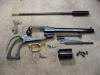 |
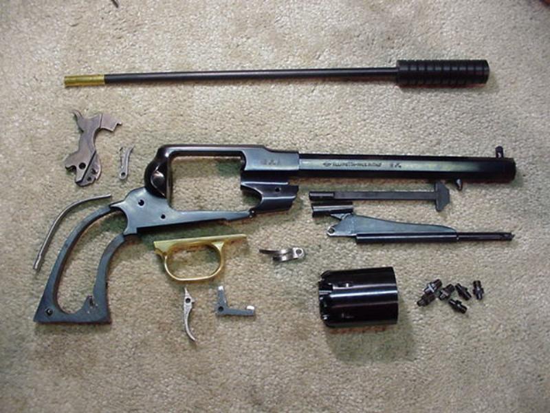
Figure 2. The Remington New Army has been taken
completely apart and is almost laid out as an exploded view, but without the
screws. This shows how simple this gun is and how easy it is to work on.
A basic set of gunsmith's screwdrivers and a nipple wrench is all that is
needed. |
| Continue taking the gun apart
by removing the mainspring tension screw at the front of the lower grip
frame. With that out, remove the hammer spring by sliding it out of
its retaining slot. Remove the screw on the left side in front of the
cylinder that holds the loading lever in the frame and slide the loading
lever assembly out the front of the ram slot. Turn the gun over and
remove the trigger guard screw and remove the guard by lifting away from the
frame and pulling slightly forward. Remove the trigger/bolt spring by
removing the screw that is just to the rear of where the trigger guard
housing screw. Turn the gun so the left side is up and remove the
trigger retaining screw and slide the trigger and cylinder bolt out the
bottom of the frame. Remove the hammer retaining screw from the left
side of the frame and slide the hammer down through the area of the trigger
guard until the hand retaining screw is visible at the bottom of the frame.
Remove the small screw that retains the hand and slide them out. The
hammer can now be moved up and removed through the top of the frame.
This completes the complete tear-down of the gun. |
|
 |
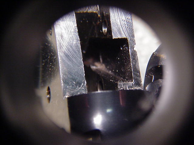
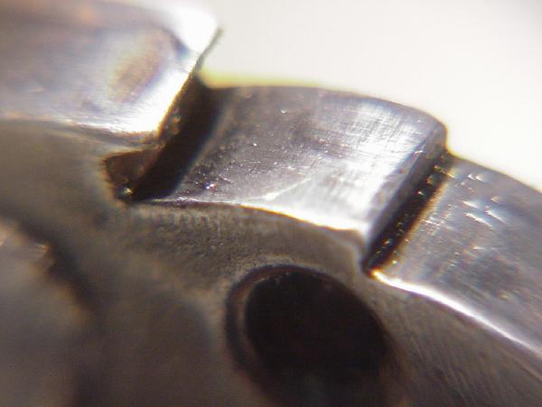
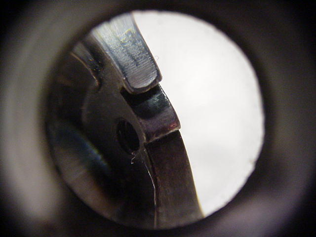
Figure 3. This photo shows the hand channel . It
rises from right to left and you can see metal about half way up that
will obstruct the hand spring. Photo on right shows the hand channel
cleaned of the casting material. |
 |
|
| Carefully examine the photos in
figure 3. The photo on the left shows the hand channel that runs from the left side of the
hammer and up to where the hand presses against the star at the rear of the
cylinder. The barrel is pointing up in this photo and the picture was
taken looking up through the removed trigger guard. Note the amount of
flashing located about half way up the channel? It resembles a speed
bump and the hand rides in this
channel with the leaf spring trying to slide right through that flashing.
We should begin by polishing the channel enough to let the hammer operate in
a reduced friction environment, but it will be difficult to remove that
metal up in the channel. One way to remove the metal is with a cold
chisel, but those are too big. In the past I have removed this metal
flashing by using the tip of an engraving tool. One of the best tools
for polishing up in these tight areas is a piece of brass purchased at the
hardware store. I found a piece that is about ten inches long,
one-quarter inch wide, and about .160 thick. This brass can be filed
to fit into the recesses of the gun and emery cloth can be glued to the
brass to make a file for reaching in to file these recesses. Old
hacksaw blades could also be ground down to serve this purpose. |
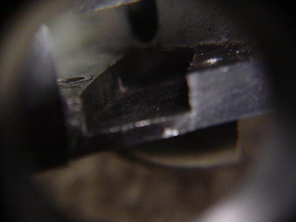
| The photo on the right shows
the hand channel from a slightly different angle. The speed bump has
been removed and the hand spring can smoothly run through that area.
This will provide a smoother feel while cocking the gun and will reduce wear
and friction on the hand spring while shooting. |
| Now we move our attention to
the sear. The sear is a critical component in the feel of the hammer
and trigger pulls. Roughness on the ramps leading to the half-cock
notch or the sear can make the hammer feel gritty and rough. Smoothing
the high spots from these ramps will make the hammer pull feel very smooth,
but does not really affect the smoothness during firing because the trigger
is not in contact with these areas when the hammer is falling. |
| The amount of stoning and
polishing needs to be addressed. The purpose of stoning is to reduce
friction and to make the moving metal parts move against each other without
having to follow a rough contour. Taking the metal down to a mirror
finish can help the action, but polishing the machine marks until they are
even reduces the chances of cutting through the case hardening and allows
little recesses to hold some lubricant. |
| The sear depth and angle are
import to the feel of the gun and represents the potential to make the gun
unsafe. Everything is a trade-off between feel and strength. A
shallow sear will allow a quick break with little trigger movement (creep),
but may not catch properly when being cocked and slight wear or damage on
the edge of the sear can cause the sear to become unreliable and may allow
accidental discharges. The fact is that creep tends to only be a
problem when someone is feeling the action and is hardly noticeable in
action shooting. I like to set the dept of the sear at .030 inches,
which is about the dept I have found on most Remington reproductions. |
| The sear angle is also
important in the feel and safety of the trigger. When the trigger and
hammer sears interlock, if the sear is on the radius line of the hammer,
then the angle is zero or neutral. This means that the movement of the
trigger does not move the hammer at all as the trigger is being pulled.
A positive angle means that pulling the trigger causes the hammer to be
cocked slightly more as the sear must move the hammer in order to clear.
This slight dovetailing of the sears should be at around 2-3 degrees to
provide a crisp trigger that will be safe and hold well. Any greater
angle is an over-engagement and creates an excessive trigger pull. A
negative angle is unsafe because there is no interlocking of the parts and
the trigger can release the hammer without being touched. |
|
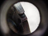 |
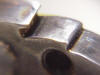
Figure 4. The hammer sear at left has only been
lightly buffed to bring out the machining marks. The one on the
right has had the machining marks smoothed and the sear has been squared
better. |
 |
|
| The photos in Figure 4
illustrate the change provided by reworking the hammer with an Arkansas
stone. The half-cock notch is cleaner, the ramps are cleaner, and the
sear is cut to about a three degree angle and is .030 in depth. The
work is not perfect, but is a significant improvement over the original sear
and it provides a crisp and clean break in action shooting. This is a very
precise process and the hobby gunsmith will get a little better with each
sear that is polished. |
| Whenever working on the sear, I
recommend that the hobby gunsmith reassemble the gun and test the trigger
for safety. Put the gun back together without the cylinder. Cock
the gun to half-cock and then put pressure on the hammer and try to push it
back in the direction of the frame. It should not move at all.
Assuming that the hammer holds well in the half-cock position, pull it back
into the full cock position and repeat the test by pushing on the hammer to
make sure the sear is engaging and holding. If hard finger pressure on
the hammer causes the sear to slip, then your gun is not safe and the sear
angle is probably negative or the sear is way too short. You should
find the break to be crisp and clean. If you are used to cartridge
revolvers, the trigger and hammer pull may seem a little strong, but this is
normal in a cap and ball revolver since the hammer must place pressure on
the cap during ignition. |
| Hardening the hammer parts. |
| After polishing the various
parts and reassembling the gun, it was time to take it to the range and test
fire it to see how many shots could be fired with the .003 barrel/cylinder
gap before the gun locked up from powder fouling. I was shooting a CAS
match that weekend so I took it with me for the test firing. I did not
think it would make it to the fifth shot, but I was very wrong. I
loaded the gun with about 25 grains of FFFg Goex blackpowder with a dab of
Crisco in front of the ball. The gun fired smoothly and accurately for
all five shots without any indication of fouling or problems. My
inspection of the gun showed it was very clean. |
| This test defied conventional wisdom that a gun this tight would continue to shoot an entire
cylinder of reasonably hot loads without any binding or problems. I
wish I could have kept firing the gun until it bound up in order to find out
exactly how much it could handle. My theory is that the unusually narrow gap
prevented much in the way of gasses and fouling from escaping between the
barrel and cylinder. This prevented gasses from getting into the
cylinder pin and causing fouling jamming. Measurements of my 1847
Walker and my two 1851 Navy Colts revealed that they were similarly tight
with gaps of .002-.003. |
| |
| |
| |
| |