Shooter from a C&B Pistol
Mohave Gambler
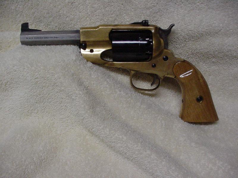
This project started a few years ago as a Remington 1858 Buffalo revolver kit bought from the Dixie Gun Works. The kit contained a brass frame that was machined and fitted for the internal parts and almost usable right out of the box. The external surfaces of the brass frame were rough cast and had to be filed and finished. The grips were fitted to the frame, but needed to be shaped to the contour of the frame, shaped for the proper appearance, and then finished to provide an attractive grip.
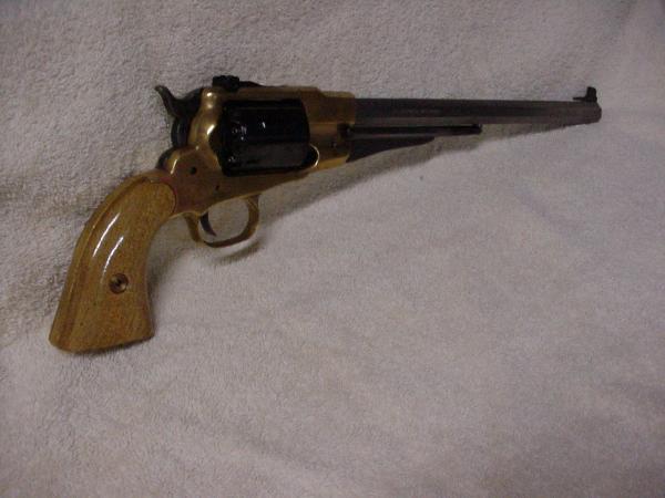
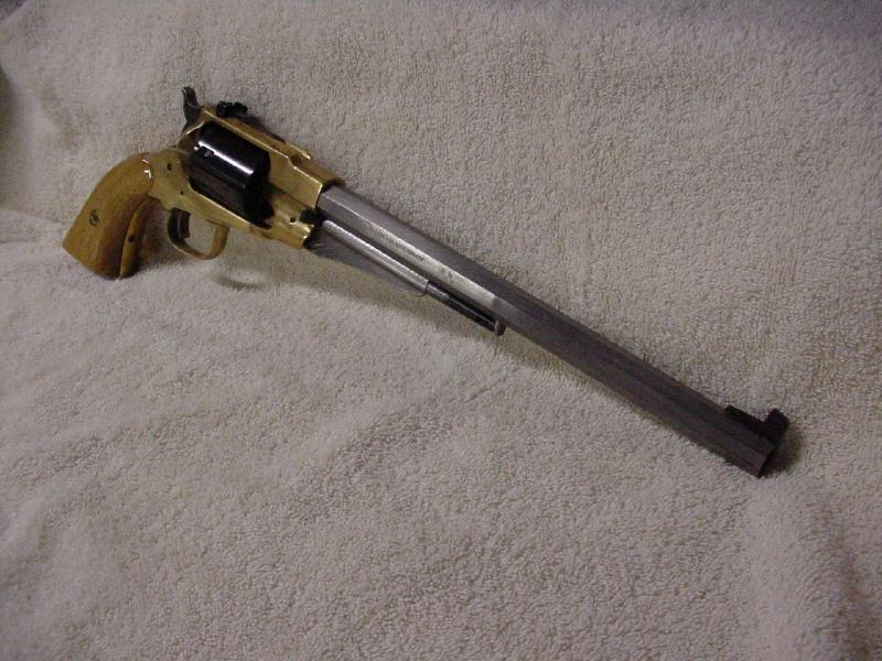
Unlike most cap and ball revolvers, the Buffalo has a twelve-inch long barrel (Please see figure 2) and modern style adjustable sights. I thought I might use it for target shooting when I built the kit, but it turned out that the sights are not very usable with that long barrel so I decided to put it in my collection and hope my children could take advantage of its uniqueness during the next century. Then I started doing Cowboy Action Shooting and things changed.
In Cowboy Action Shooting, the shooter is placed in a class based upon the type of gun, the powder used, or the shooting style. Cowboy Action Shooting has a single classification for pistols with adjustable sights, which is the modern class. This requires the Remington Buffalo to be used in the Modern Class where it must be shot against competitors using Ruger Blackhawk firearms. I have been known to shoot Blackhawk revolvers in the Modern class so I decided I would modify the Buffalo to be a backup gun.
The beginning of any gun building or modification project should be with the end in mind. I write down what the finished product will look like and this becomes the mission statement to keep the project on track. The mission statement for the Buffalo is as follows:
Remington New Army Project Statement
To convert the existing Remington 1858 Buffalo revolver into a CAS Modern Class revolver with a barrel length between four and six inches. The gun should be aesthetically pleasing and remain as true as possible to the appearance of the original Remington revolvers. Secondarily, if reasonably possible, to convert the Remington Buffalo revolver to accept metallic cartridges.
Barrel Length
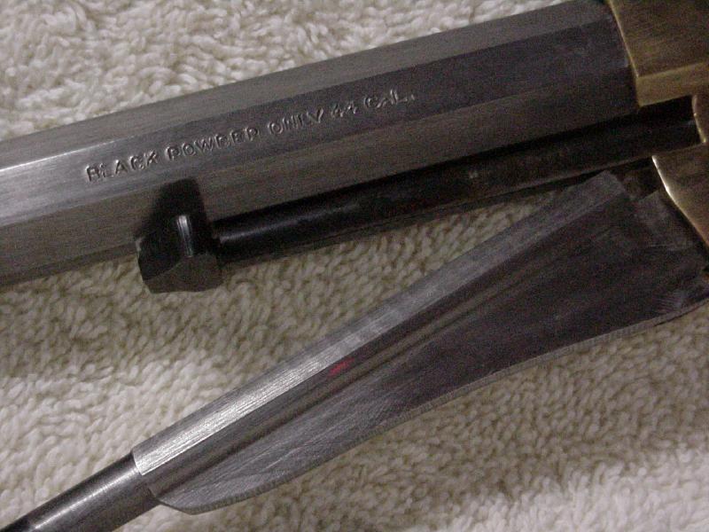
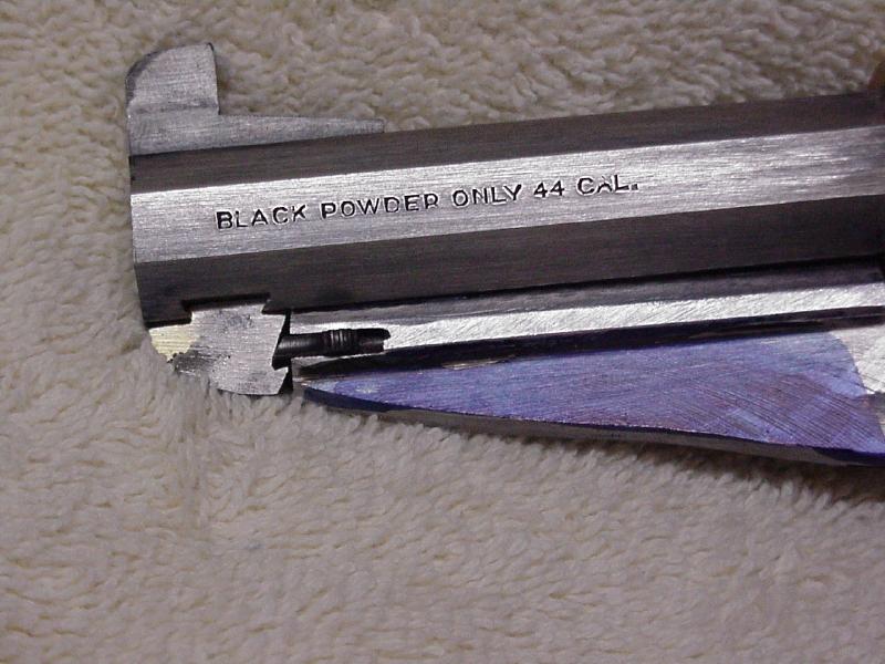
There are several factors that determine the optimum length of the barrel on this project. The first 1.5 inches of barrel are inside the frame of the gun. The cylinder pin extends out to about the four-inch point when moved out enough to remove the cylinder. The loading arm lock is located at about 6.5 inches down the barrel. The barrel can only be cut down to about six inches without having to make a removable loading arm latch. In summary, the barrel can be cut down to about 6.5 inches and will only require the machining for the reinstallation of the front sight. Cutting it any shorter will require considerably more machining and changes to the gun. I decided to cut the barrel to 4 ¾ inches as measured from cylinder to the end of the barrel. This length was selected because it allows the barrel to retain the original Pietta brand stamping along with the warning for only shooting black powder (Please see Figure 3). This length will require that I shorten the loading arm, fabricate a new loading arm latch that is removable, and to reinstall the front sight.
Cartridge Conversion
Attempting a cartridge conversion on this project introduces several problems. I originally considered doing my own conversion from a set of plans, but decided it would be too complex and the project might become a paperweight. That reduced the options to the R&D conversion kit or the Kirst Konverter.
The R&D converter consists of a replacement cylinder that is removed from the frame and the rear section is removed to reload. After reloading the chambers, the chamber is reinstalled in the frame and the shooter continues. This kit is probably more historically correct, but there are many like this and it represents no challenge to install.
The Kirst Konverter is also a two-piece option that is similar to the colt conversions that were done after the War Between the States. The original Kirst had to be removed like the R&D converter, but a newer option is the ported version that can remain in the frame during shooting and the owner must file a loading port in the frame of the gun.
All cartridge converters have several disclaimers that they are not to be used with brass-framed guns. That presents a bit of a problem since mine has a brass frame. The Kirst warnings indicate they are made for Blackpowder or Cowboy Action equivalent cartridges only. It appears that smokeless CAS loads would be acceptable in the steel frame guns as long as the loads are kept fairly low. I am assuming that the brass-frame guns are not strong enough for those smokeless CAS loads, but that it should be safe to use a normal blackpowder load in a brass frame gun. This will require more testing when my Ported Kirst Konverter arrives.
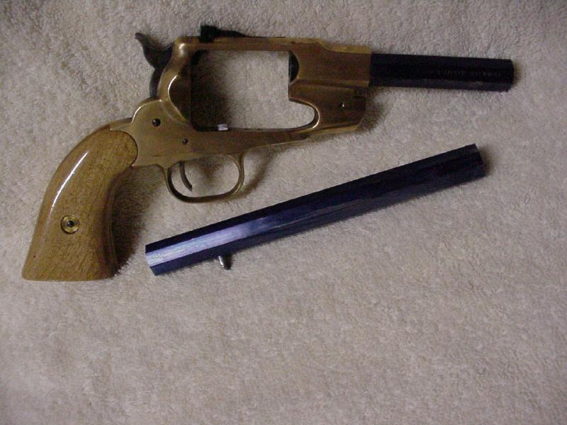
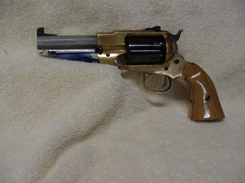
After deciding to cut the barrel down to 4 ¾ inches, I coated the barrel with Dykem so that I can scribe lines for filing and machining. The most difficult part of starting any such project is actually taking the hacksaw to a perfectly good firearm. Having said that, I measured 4 ¾ inches down from the cylinder and scribed the cut lines in the blue Dykem. I wrapped some electrical tape around the barrel at the cut line to protect the barrel, clamped the barrel in a vice, and proceed to carefully saw off the end of the barrel. I then took a file and squared and cleaned up the hacksaw cut. There was no turning back at this point and the results can be seen in Figure 4.
With the barrel cut and squared, I used the old barrel to measure and lay out the new dovetailed channel needed to accept the front sight. This is an unusual dovetail because it runs from the end of the barrel and in for about a half inch. Most dovetails pass across the barrel and can be easily filed, but this one is a blind cut. There are many good ways to cut the dovetail channel, but the best is to use an expensive milling machine. I don’t have access to a milling machine, but my drill press looks a bit like one so I decided to see if it would work to mill the slot.
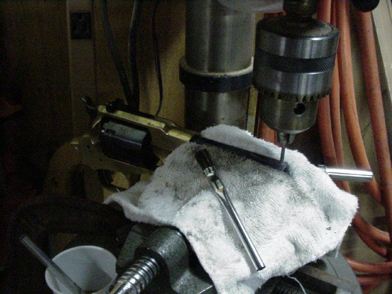
Figure 5. Using the drill press to “mill” the slot for the front sight.
A milling machine is simply a very heavy-duty steel cutting router mounted on a very heavy platform to allow the cutting of steel to close tolerances. It is made very versatile by the fine adjustments. It has been my opinion that small carbide cutting tools, normally used in hand-held grinders, could be used in a drill press to slowly cut a reasonably precise slot. I clamped a cross-sliding vice to the table of the drill press, clamped the gun barrel into the vice, put a 1/8 inch carbide cutting tool in to the chuck, and slowly used the controls of the vice to move the work under the cutter. I made sure the cutter was lubricated and cutting went much better than I had expected (Please see Figure 5). After cutting the slot, I changed over to a tiny dovetail cutter, which worked, but was simply too small to be used much in this oddball manner. Dressing up the slot with small files allowed the front sight to be reinstalled to look like the original.
With the barrel cut to the new dimensions, it is time to tackle the loading lever. The original Pietta Remington used a round post with notches to hold the loading arm in place. I considered making a new round post and silver soldering it into place, but that would have made it impossible to remove the cylinder pin. My earlier measurements and planning revealed that the cylinder pin would have to pass through the area of the latch pin if the barrel were cut this short, so the plan was to make a removable latch pin. I dovetailed a larger post into place so that it can be easily removed to allow the removal of the cylinder pin for cleaning.
As I started designing the new latching mechanism, the project moved from the mechanics of cutting and milling to the art of creating the correct aesthetics that will be pleasing to the eye. The Remington has a curved and flowing flag that strengthens the loading arm while providing its distinct image. I decided to have the flowing shape of the flag extend into the latch and then flow up to the end of the barrel. This not only allowed me to retain the flowing lines of the original loading arm, but allowed me to make a much larger and stronger loading arm latch. The new pin was made by taking a piece of scrap steel, marking it with blue dye, and using a scribe to lay out the lines of the new latch pin. I used the dimensions of the old pin to assure the latch would still work. Using a variety of files, I removed metal that was not needed for the pin. Figure 7 illustrates the shape of the new dovetailed pin installed in the barrel of the gun.
With the dovetailed loading arm latch set into place, the loading arm could not close because it extends about two inches beyond the end of the barrel. I scribed a line in the blue dye that would allow the loading arm to almost close, clamped it in a vice, and cut off the excess metal of the arm. I used a file to slowly shorten the loading arm until it hinged into place with approximately the same clearances as the original. I used a small drift punch to remove the retaining pin from the original loading lever arm retaining latch so I could use the original parts. The latch consists of a spring loaded sliding pin with thumb grips that ride in a notch. Using the original latch as a guide, I used the drill press to drill a new recess hole down the center of the shortened loading arm to received the spring and the latch. I then rough cut the slot for the thumb grips and filed the slot to the same dimensions as the original. A new hole needed to be cut across the latch to reinstall the drift pin that holds the latch together.
The Ported Kirst Konverter arrived as the Remington was taking shape. I removed the cylinder and installed the conversion kit. The kit was a drop-in that required almost no modification. I did have to make some changes to the hand on this particular gun, but since the Konverter properly fit into my other two Remington revolvers, I will not address the changes I made because I know the problem is unique to this gun and some changes I made to it last year.
The first task was to cut a loading port on the right side of the recoil shield to facilitate loading. This was done by using Dykem to allow me to mark the brass on the cylinder side of the recoil shield. I carefully filed away with a rattail file until I was able to slide a .45 ACP cartridge into the cylinder and extract the spent casing.
Because the gun has a brass frame, I wish to respect the problems associated with frame strength. My concern is that the .45 ACP cartridge will only hold about 20 grains of blackpowder, which might be just a little weak. The first cartridges I loaded were done using 20 grains of Hodgdon 777 blackpowder substitute. This powder was designed for blackpowder hunting and has more power for a given amount of powder. I felt this would give the equivalent performance of closer to 25 grains of normal blackpowder. I loaded my cartridges with powder and then pressed a .451 diameter round ball into the front of the cartridge and gave it a light crimp. The bullets look a little unusual for someone accustomed to normal ammunition, but the distinctiveness should help differentiate this ammunition from anything that belongs in a gun with a steel frame.
The trip to the range was exciting and anti-climatic. The gun shot fine and the groups were about one inch in size at the ten to fifteen yard range normally associated with Cowboy Action Shooting. This gun quickly turned into a keeper.
As things started coming to a close on this project, there were only two items remaining to be completed in order to call the project a completed success. I still needed to put a finish on the gun and to build the extractor tube and rod for the right side of the barrel. Although the metal finish went well, the extractor turned out to be a problem. I will happily add that to the web site instructions after I figure out how I will solve it.
Metal Finishing
My goal was to make the gun appear as if it might be an original cartridge conversion from the Civil War era. In order to do this, I chose to use a rust brown finish that is similar to what the original finish might deteriorate to over the years. I decided to try Barrel Brown and Degreaser, by Laurel Mountain Forge. It can be obtained from Brownells. I selected the Laurel Mountain browning solution, because it would not be necessary to be as careful about oil contamination on the metal parts.
I began by removing the bluing from the Kirst Konverter. I did this by using a product called Navel Jelly. Navel Jelly is normally used to remove rust from tools and parts. The bluing on a gun is essentially a form of controlled rust so the Navel Jelly does an excellent job of removing the finish.
Site Design By Time-Slice Check Us Out.....